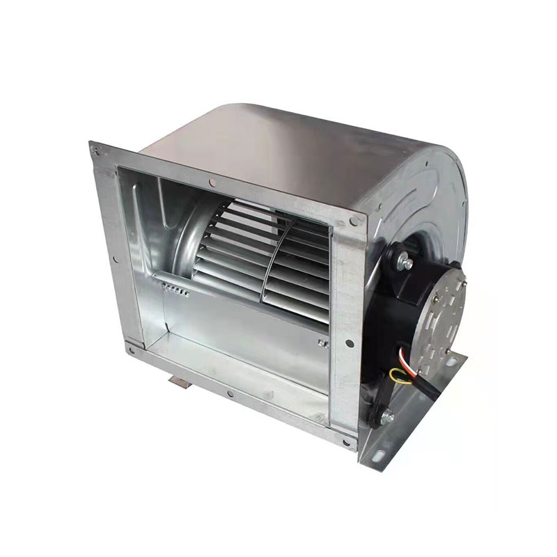
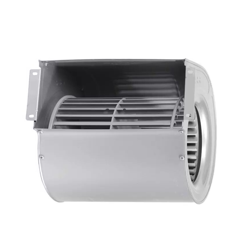
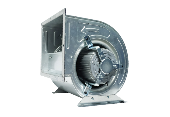
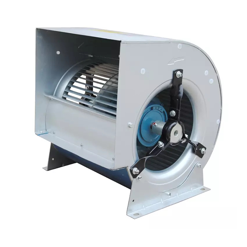
A centrifugal fan is one of the most efficient fans currently. Here Tingertech will tell you everything you need to know about centrifugal fan, or called furnace blower.
Here, Tingertech will answer questions of :
A centrifugal fan or furnace blower or centrifugal blower or centrifugal duct fan or housing fan includes an impeller, squirrel cage, motor and other small parts. It pulls the air inside the blower and then pushes it out at a 90º angle. The two main components of a centrifugal fan that moves air are the motor and the impeller. An impeller sucks or pulls air, in contrast to a propeller which pushes air.
Some fans can pull and push air at lower than a 90º angle; these fans are called mixed flow fans.
Centrifugal fans can either have no exterior housing or structure to offer protection or they can be built with some protective housing.
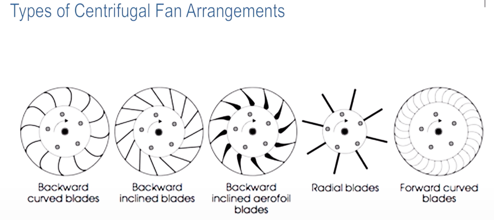
As shown in the video below, there are five different types of centrifugal fans, which differ based on the type and shape of the fan blades.
A centrifugal fan or furnace blower is typically used for residential applications to move air through a duct, like furnace, or range hood duct and other air conditioning system. Also you might see centrifugal fan used in commercial environments, for example your car wash. These fans are all centrifugal fans or furnace blower. They take the outside air and move it rapidly, creating a pressure differential. As long as the pressure differential is maintained, the air will continue to flow and your car will dry out quickly. Centrifugal fan is also commonly used in air conveyor devices, which use air to transport objects along a conveyor belt. In a factory or warehouse, you may see it.
What are the different types of fans?
There are:
·Backward curved blades centrifugal fan
·Backward inclined blades centrifugal fan
·Backward inclined aerofoil blades centrifugal fan
·Radial blades centrifugal fan
·Forward curved blades centrifugal fan
Below is a chart to help you differentiate between these types of centrifugal fans.
Forward Curved Motorized Impeller
When we define the required volume flow, whether it is supplying fresh air or process cooling, we need to combine this with the flow resistance that the fan encounters in the application. Volumetric flow (in m3/hr) and pressure (in Pascals - Pa) combine to be the operating point at which the fan must operate. It is important that the performance characteristics of the fans we choose meet the desired operating point at or near the peak efficiency point. Using the fan at maximum efficiency minimizes power consumption and noise from the fan while delivering the performance you need.
The name "centrifugal fan" or "furnace blower" comes from the direction of flow and how air enters the impeller axially and then pushes outward from the outer circumference of the fan. The difference in flow direction for forward and backward curved centrifugal fans is the direction in which the air leaves the circumference of the impeller. For a backward-curved impeller, the air exits radially, while for a forward-curved impeller, the air exits tangentially from the circumference of the fan.
Forward curved centrifugal blower or furnace blower are characterized by a cylindrical shape with many small blades around the impeller. In the example shown below, the fan rotates in a clockwise direction.
Unlike backward-curved impellers, forward-curved impellers require a housing that converts high-velocity air leaving the tips of the impeller blades into lower-velocity static forces. The shape of the housing also directs the airflow to the outlet. This type of fan housing is often referred to as a scroll; however, it may also be called a volute or sirocco. By installing the forward curved impeller in the scroll housing, we usually refer to it as a forward curved blower.
The best working area for forward curved centrifugal fan, housing fan or furnace blower is when working at higher pressures. Forward curved centrifugal blower or furnace blower works best when high pressure is required for lower flow rates.
Caution should be exercised when selecting a forward bend blower to operate at low pressure and maximum volume flow. At this point, the impeller operates at an aerodynamic stall in the same way that an axial fan operates at the saddle point of its curve. At this point, noise and power consumption will peak due to turbulence.
The peak efficiency is located at a point called the knee of the characteristic curve. At this time, the ratio of the output power of the fan (volume flow (m3/s) x static pressure development (Pa) to the input electric power (W) is the largest, and the sound pressure generated by the fan is at its quietest time.Above and below the optimal operating range, the airflow through the fan becomes noisier and the efficiency of the fan system decreases.
The benefit of using a single entry forward curved motorized impeller is that it has a steep fan characteristic. This is especially useful in systems that require a consistent level of filtration. As air passes through a particulate filter the filter arrests airborne dust and pollen, the finer the grade of filtration the smaller the particles arrested by the filter. Over time, the filter will become more and more clogged with dirt and debris, requiring more pressure to deliver the same amount of air. Using an impeller with a steep characteristic curve in this case means that as the filter becomes more and more clogged,the volume flow remains constant while the pressure across the filter is increasing.
The benefit of using a dual inlet forward curved impeller is that it can provide a large flow through a relatively small size blower. The compromise with using a double inlet blower is that it has a lower pressure development, which means it can only be used with lower pressure systems.
As mentioned earlier, the forward-curved motorized impeller produces high-velocity air at the blade tips, which needs to be directed and decelerated to convert dynamic pressure into static pressure. To facilitate this, we build a vortex around the impeller. The shape is created by the ratio of the distance from the center of the impeller to the fan outlet. Both mounting considerations are shown in the following figure:
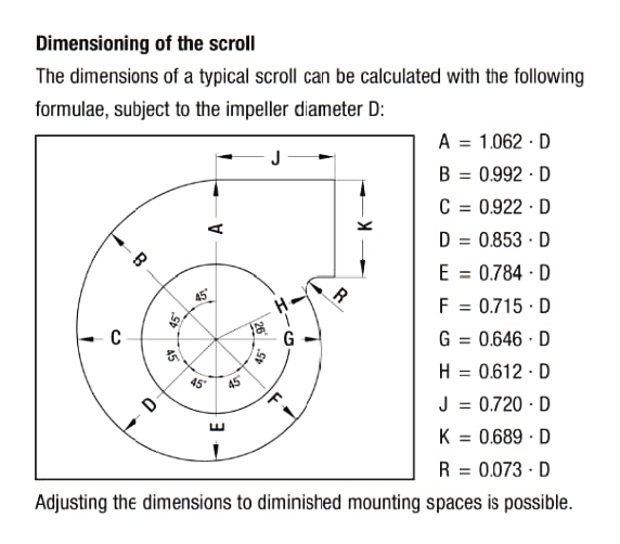
The inlet ring diameter should allow only a small gap between the impeller and the ring to avoid air recirculation.
Mounting considerations - Clearances
It is important to ensure the suction of the housing fan or furnace blower and adequate clearance on the sides.
Insufficient clearance on the suction side of the fan increases the inlet velocity, resulting in turbulent flow. This turbulence increases as the air passes through the impeller, which reduces the efficiency of energy transfer from the fan blades to the air, resulting in more noise and reduced fan efficiency.
When the desired operating point falls within the fan characteristic region of higher system pressure and lower volumetric flow, single-entry front-bend centrifugal fans should be considered. If the application requirement is for high flow in a confined space envelope, a dual inlet forward bend centrifugal fan should be considered.
When the desired operating point falls in an area where the system pressure is higher and the volumetric flow rate is lower on the fan characteristics, a single inlet forward bend centrifugal fan should be considered. If the application requirement is for high flow in a confined space envelope, a dual inlet forward bend centrifugal fan should be considered.
The housing fan or furnace blower should be selected within its optimum range, which is at what is called as the knee of the characteristic curve. The peak efficiency point is closer to the high pressure limit on the fan's characteristic curve, where it also operates at its quietest. Operation outside the optimum range (at the extremes of high flow) should be avoided as the turbulence at these points and the aerodynamic efficiency of the impeller blades can create noise and the impeller will also run in aerodynamic stall. At low pressure and high flow, the operating temperature of the motor under load should be considered, as the motor may overheat.
The air on the inlet side of the impeller should be as smooth and layered as possible. For maximum efficiency, a clearance of at least 1/3rd the diameter of the impeller should be left at the fan inlet. Using an inlet ring (inlet nozzle) that overlaps the impeller inlet will help eliminate flow disturbances before the air passes through the fan, reducing noise caused by turbulence, keeping power consumption at the operating point to a minimum and maximizing efficiency.
Steep operating characteristics, the higher pressure capability of the single inlet blower, and the high flow capability of the dual inlet blower mean that front bend fans are a useful option to consider in a variety of installations. Contact us for more details!
